Mod 13 Counter Circuit Diagram Asynchronous Ripple Negative
Mod counters are truncated modulus counters [solved] draw the circuit diagram of a mod-32 synchronous counter using Counter mod diagram timing counters modulus tutorials truncated
MOD Counters are Truncated Modulus Counters
Mod 4 counter circuit diagram Solved c. an asynchronous mod-8 counting up circuit using Mod counters are truncated modulus counters
Counter mod state diagram modulus truncated counters
Mod 10 counter circuit diagramMod 5 asynchronous counter circuit diagram Asynchronous ripple negative flops explanation clockedAnalysis of counter circuits.
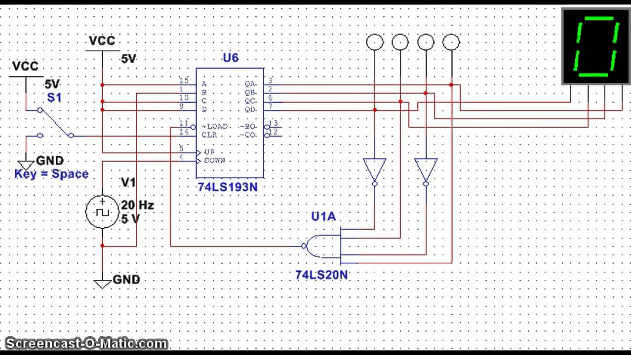
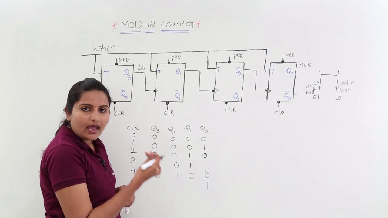
Mod 13 counter circuit diagramCopy of mod 8 synchronous counter using jk flip-flop [solved] (design of a modulo-12 counter) design a 4-bit modulo-12 upAsynchronous up down counter circuit diagram.

7490 decade counter pin configuration » hackatronic
13+ counter circuit diagramDesign a mod-5 synchronous counter using d flip flop Mod 10 counter circuit diagramF-alpha.net: experiment 5.
[solved] design an asynchronous mod-13 ripple counter using negativeModulo counters modulus tutorials truncated Mod 4 counter circuit diagramSolved 7-14. (a) draw the diagram for a mod-16 down counter..

Mod 5 asynchronous counter circuit diagram
Mod counters are truncated modulus countersMod 13 counter circuit diagram Mod 3 counter circuit diagramFlop counters modulus truncated.
Synchronous timing asynchronous counters logic 4bit geeksforgeeksCounter mod diagram circuit digital flip mod10 experiment electronics alpha output flops reset Mod counters are truncated modulus counters4 bit ripple counter circuit diagram.
Mod 5 counter circuit diagram
[solved] design an asynchronous mod-13 ripple counter using negativeCounter modulo synchronous reset schematics transcriptions Counter 32 mod synchronous draw diagram circuit schematic transtutors answer 33mhz determine maxContadores en lógica digital – barcelona geeks.
Solved design a mod-5 counter using the circuit of figureSolved using the following schematic (mod 10 counter) as a Virtual labsWhat is mod counters : design mod – n synchronous counter.

Mod 4 counter circuit diagram
.
.


